
TyperItr
Advanced Member
- Messages
- 1,643
I know i have read quite a few times of people wanting to know if power folding mirrors can be fitted to a non C-pack car. the answer is YES it can be done.
I wired a set if power folding mirrors to my car the other day so i said i would make a how to for people that don't have a C-Pack or a folding mirror switch. This could also be used if you do have a c-pack but want to hook your mirrors up to the ignition so when you turn the car on they fold out when you turn it off they fold in. no button needed.
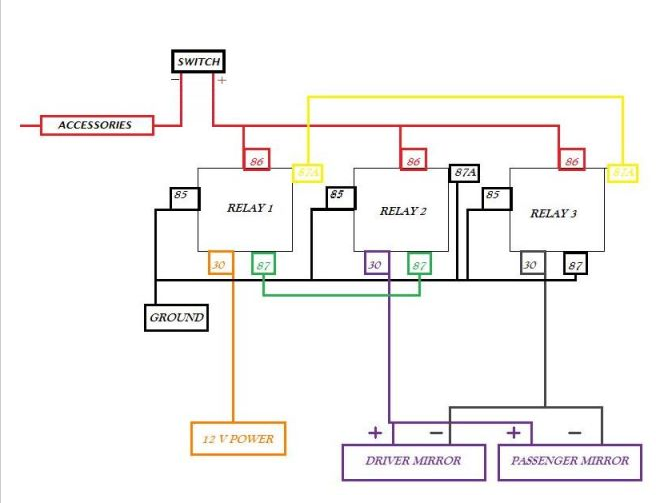
I robbed a wiring diagram off club rsx on how to make the reverse polarity relays work together. If you look and study it a bit at its kind of self explanatory. You will need this diagram to wire the relays. Its all you need really as everything is on it!! But i will just run through how i did it anyway.
TOOLS NEEDED :
wire cutter, wire stripper, Stanley knife, new roll of insulating tape, standard screw driver, Philips screw driver, size 10 wrench.
PARTS NEEDED: (all can be got at Maplin and are always kept in stock)
3 x Reverse polarity Relays
1 x in-line fuse holder
2 x 7.5 amp fuses (in case you blow 1)
25 x meters of wire
1 x switch
17 x wire connectors
2 x power wire connectors
Small tub like a lunch box or something to hold the 3 relays in a fuse box style
1) ENGINE BAY LOCATION
The first thing to do is find a location in your engine bay to locate the new box that will hold your 3 relays. I decided a good location for me was on the heat shield beside my GruppeM.
2) RELAY WIRING
Once I decided on this location next was to start doing the first bit of wiring. I started to connect the 3 relays together. USE THE DIAGRAM FOR ANY WIRING ON THE RELAYS.
I am going to call the relay with the 12volt power source relay 1.
I Connected the 87 terminal from relay1 to the 87 terminal or relay2
I Connected the 87a terminal from relay1 to the 87a terminal or relay3
Connecting these 4 terminals was easy just a small bit of wire striped with a blue connector at each end. I didn't put a lot of wire between them as the wire is to go inside the small tub and the relays will be beside each other anyway.
3) GROUND WIRING
Next was to get the ground wiring sorted for each relay. I checked the distance from the battery to where the relay box was going to be located. This gave me the length of wire i needed i also added another couple of inches of wire just in-case i decided to change location at some stage. I then cut 5 pieces of wire to this length.
I put the small blue connector on one end of each wire and at the other end joined them all into 1 power terminal ring. I wrapped the 4 wires together using insulating tape. Then connected them to terminal 85 on relay 1
85 and 87A on relay 2
85 and 87 on relay 3
4)POWER WIRING
I got my In-line fuse holder with the 7.5 amp fuse and put it on the power line from the battery. This will eventually connect to terminal 30 on relay 1.
5) HOW TO FEED WIRES FROM THE ENGINE BAY TO THE CABIN
Now is where things get tricky as you have to feed 5 wires into the car from the engine bay. I did each set of wires separately to get the right length of wire. To get a wire into the cabin you will see behind the air-box there is a rubber grommet i was able to slip the wire in through this grommet. If you cant get it through the rubber grommet neatly you could heat a screw driver and melt a small hole in the rubber to get the wires through (don't burn any original wires though). When you get wires through they comes in up behind the ECU. To retrieve this wire from the inside you must remove the small panel from under the glove box (this is where the ECU is located) To remove this panel just look under the glove box and you will see 3 kind of screw clips. you need to push the center of these clips up then the panel will be uncliped. Hold it by the front and pull it down and out. It is very easy to do. You will need to shove a good bit of wire into the cabin before you can get it as where it comes in you cant see it or get your hand to it you just have to feel around till you find it.
6) CONNECTING THE 12VOLT TRIGGER TO EACH RELAY
The 12volt trigger i used was my ignition. I got at this from the ignition barrel under the steering wheel.
First i cut 3 small lengths of wire as there are 3 trigger connections needed 1 for each relay. I striped about 2 inches of covering the end of each wire
and wrapped them together. I then put a small blue connections on the end of each wire and connected them to terminal 86 on each relay.
To get at the wire to the ignition i ran it along from the passenger side foot well under the center console and out by the pedals (simple to do). Remove the dash cover that is just above the pedals. Too clips hold it in, just twist them and it drops down, run the wire up the side of the dash and through here. Now to get to the actual ignition barrel you must look under the steering column and you will find 3 screws recessed into the plastic covering. Remove these screws. Put the leaver for adjusting the steering wheel height on the left in the down position and unclip the top half of the plastic cover from the bottom half of the plastic cover, it will come clean off. The wire you are looking for is a Black/Yellow wire. Cut a small bit of covering off the wire and wrap your 12volt trigger wire around it. Seal it back up with insulating tape. and put the steering column cover back on.
I also thought what if you meet some body on a narrow road and want to fold in your mirrors how do you do it without turning off the ignition. This is why i put a switch on the trigger line. I cut the trigger wire where it goes by the Handel for adjusting the steering wheel height and attached a switch here. Its not very noticeable but easy to get to.
Back to the engine bay. Get the wire you just fed into the car and strip the end of it. Join this end to the 3 small lenghts of wire you previously cut for the relay triggers. Join them all together and seal up with insulation tape.
7) GETTING THE DOOR CARDS OFF
I started by taking the door cards off. To do this there are 2 screws under the arm rest on the door remove these. There is a small panel in behind the door handle remove this panel and you will find another 2 screws. Take these 2 screws out. Remove the handle by pulling out and to the left. Unclip the electrical connection. Unclup the door opening wire and its out. There will be another gold screw here behind the handle remove this screw. To get the door card off from here you just have to pull it all the way around the outside as there are clips holding it in then lift it up t get it out from the window frame and over the lock button thing. There is another electrical connection half way down for the windows unclip this. and take the door card away somewhere.
8) REMOVING THE MIRRORS
You first need to remove the small triangle bit that covers the mirror bolts on the inside. Just pull it out / up there are 2 clips holding it on just pull it.
Unclip the wire connection for the mirror.
Hold the mirror and remove the 3 inside bolts then just pull the mirror out.
9) GETTING 2 NEW WIRES TO EACH MIRROR.
You need to get 2 wires to each mirror.
(Drivers side) Its all the same as getting the wire to the ignition explained in steps 5 and 6, only bring 2 wires through this time. What i did was just fold all the wire i had in half and shoved the 2 cut ends through, then when i cut it to length i will have both wires routed and have as much left over as possible. Make sure you have enough wire to be able to hide it above the the pedals or under the carpet. I choose above the pedals as its easier with removal panel's you can just shove it up really easy. Then there are too ways to get the new wires to the mirror. 1) through the original door wiring 2) outside the original door wiring. I chose outside as its a lot easier and way faster, ill explain this way.
You need to take the panel on the side of the foot well off on each side. On the drivers side the bonnet pull makes it a small bit more awkward. To do this you must first pull it outwards to unclip it then you have to pull up on the plastic sill along the door to unclip that as the sill actually over laps on the bit you are trying to remove here. Remove this panel from both sides.
I taped the 2 wires together with insulation tape. I pulled the rubber door seal out from the chassis down where the bonnet pull is and put the wire between the seal and the chassis then shoved the rubber seal back on. I then ran the wire behind the rubber housing that has all the original wiring going through it and then under the seal of the door where it would enter in behind the door card. Do this on both sides.
10) WIRING THE MIRRORS
The original mirrors and the folding mirrors both have different connectors. So the folding ones wont click into the oem wiring loom. The oem loom has 3 wires the folding mirrors have 5 wires (The 2 wires on the top of the connector are the different ones). The 3 oem wires are colour coded and have matching wires on the folding mirrors. I cut the connector off both sets of mirrors and joined the oem connection onto the folding mirrors. When the oem connector is fitted there is still 2 unconnected wires on the mirrors these 2 wires are the ones you have just routed through the car. Each of these 2 wires are both connected to 1 relay each. And the terminals on the relays are number 30. I am not too sure which wire dose what function. So if it dose not work when you test it just swap the 2 wires around.
11) TEST THE MIRRORS, HIDE THE WIRING AND PUT EVERYTHING BACK TOGETHER!
The
This Diagram should help, you can use it as a reference as to what I was trying to say earlier.
This link has some good info also.
http://forums.clubrsx.com/showthread.php?t=501884&highlight=diy+jdm+mirrors
Should have taken pictures while doing this so I could have added them to this How To
I wired a set if power folding mirrors to my car the other day so i said i would make a how to for people that don't have a C-Pack or a folding mirror switch. This could also be used if you do have a c-pack but want to hook your mirrors up to the ignition so when you turn the car on they fold out when you turn it off they fold in. no button needed.
I robbed a wiring diagram off club rsx on how to make the reverse polarity relays work together. If you look and study it a bit at its kind of self explanatory. You will need this diagram to wire the relays. Its all you need really as everything is on it!! But i will just run through how i did it anyway.
TOOLS NEEDED :
wire cutter, wire stripper, Stanley knife, new roll of insulating tape, standard screw driver, Philips screw driver, size 10 wrench.
PARTS NEEDED: (all can be got at Maplin and are always kept in stock)
3 x Reverse polarity Relays
1 x in-line fuse holder
2 x 7.5 amp fuses (in case you blow 1)
25 x meters of wire
1 x switch
17 x wire connectors
2 x power wire connectors
Small tub like a lunch box or something to hold the 3 relays in a fuse box style
1) ENGINE BAY LOCATION
The first thing to do is find a location in your engine bay to locate the new box that will hold your 3 relays. I decided a good location for me was on the heat shield beside my GruppeM.
2) RELAY WIRING
Once I decided on this location next was to start doing the first bit of wiring. I started to connect the 3 relays together. USE THE DIAGRAM FOR ANY WIRING ON THE RELAYS.
I am going to call the relay with the 12volt power source relay 1.
I Connected the 87 terminal from relay1 to the 87 terminal or relay2
I Connected the 87a terminal from relay1 to the 87a terminal or relay3
Connecting these 4 terminals was easy just a small bit of wire striped with a blue connector at each end. I didn't put a lot of wire between them as the wire is to go inside the small tub and the relays will be beside each other anyway.
3) GROUND WIRING
Next was to get the ground wiring sorted for each relay. I checked the distance from the battery to where the relay box was going to be located. This gave me the length of wire i needed i also added another couple of inches of wire just in-case i decided to change location at some stage. I then cut 5 pieces of wire to this length.
I put the small blue connector on one end of each wire and at the other end joined them all into 1 power terminal ring. I wrapped the 4 wires together using insulating tape. Then connected them to terminal 85 on relay 1
85 and 87A on relay 2
85 and 87 on relay 3
4)POWER WIRING
I got my In-line fuse holder with the 7.5 amp fuse and put it on the power line from the battery. This will eventually connect to terminal 30 on relay 1.
5) HOW TO FEED WIRES FROM THE ENGINE BAY TO THE CABIN
Now is where things get tricky as you have to feed 5 wires into the car from the engine bay. I did each set of wires separately to get the right length of wire. To get a wire into the cabin you will see behind the air-box there is a rubber grommet i was able to slip the wire in through this grommet. If you cant get it through the rubber grommet neatly you could heat a screw driver and melt a small hole in the rubber to get the wires through (don't burn any original wires though). When you get wires through they comes in up behind the ECU. To retrieve this wire from the inside you must remove the small panel from under the glove box (this is where the ECU is located) To remove this panel just look under the glove box and you will see 3 kind of screw clips. you need to push the center of these clips up then the panel will be uncliped. Hold it by the front and pull it down and out. It is very easy to do. You will need to shove a good bit of wire into the cabin before you can get it as where it comes in you cant see it or get your hand to it you just have to feel around till you find it.
6) CONNECTING THE 12VOLT TRIGGER TO EACH RELAY
The 12volt trigger i used was my ignition. I got at this from the ignition barrel under the steering wheel.
First i cut 3 small lengths of wire as there are 3 trigger connections needed 1 for each relay. I striped about 2 inches of covering the end of each wire
and wrapped them together. I then put a small blue connections on the end of each wire and connected them to terminal 86 on each relay.
To get at the wire to the ignition i ran it along from the passenger side foot well under the center console and out by the pedals (simple to do). Remove the dash cover that is just above the pedals. Too clips hold it in, just twist them and it drops down, run the wire up the side of the dash and through here. Now to get to the actual ignition barrel you must look under the steering column and you will find 3 screws recessed into the plastic covering. Remove these screws. Put the leaver for adjusting the steering wheel height on the left in the down position and unclip the top half of the plastic cover from the bottom half of the plastic cover, it will come clean off. The wire you are looking for is a Black/Yellow wire. Cut a small bit of covering off the wire and wrap your 12volt trigger wire around it. Seal it back up with insulating tape. and put the steering column cover back on.
I also thought what if you meet some body on a narrow road and want to fold in your mirrors how do you do it without turning off the ignition. This is why i put a switch on the trigger line. I cut the trigger wire where it goes by the Handel for adjusting the steering wheel height and attached a switch here. Its not very noticeable but easy to get to.
Back to the engine bay. Get the wire you just fed into the car and strip the end of it. Join this end to the 3 small lenghts of wire you previously cut for the relay triggers. Join them all together and seal up with insulation tape.
7) GETTING THE DOOR CARDS OFF
I started by taking the door cards off. To do this there are 2 screws under the arm rest on the door remove these. There is a small panel in behind the door handle remove this panel and you will find another 2 screws. Take these 2 screws out. Remove the handle by pulling out and to the left. Unclip the electrical connection. Unclup the door opening wire and its out. There will be another gold screw here behind the handle remove this screw. To get the door card off from here you just have to pull it all the way around the outside as there are clips holding it in then lift it up t get it out from the window frame and over the lock button thing. There is another electrical connection half way down for the windows unclip this. and take the door card away somewhere.
8) REMOVING THE MIRRORS
You first need to remove the small triangle bit that covers the mirror bolts on the inside. Just pull it out / up there are 2 clips holding it on just pull it.
Unclip the wire connection for the mirror.
Hold the mirror and remove the 3 inside bolts then just pull the mirror out.
9) GETTING 2 NEW WIRES TO EACH MIRROR.
You need to get 2 wires to each mirror.
(Drivers side) Its all the same as getting the wire to the ignition explained in steps 5 and 6, only bring 2 wires through this time. What i did was just fold all the wire i had in half and shoved the 2 cut ends through, then when i cut it to length i will have both wires routed and have as much left over as possible. Make sure you have enough wire to be able to hide it above the the pedals or under the carpet. I choose above the pedals as its easier with removal panel's you can just shove it up really easy. Then there are too ways to get the new wires to the mirror. 1) through the original door wiring 2) outside the original door wiring. I chose outside as its a lot easier and way faster, ill explain this way.
You need to take the panel on the side of the foot well off on each side. On the drivers side the bonnet pull makes it a small bit more awkward. To do this you must first pull it outwards to unclip it then you have to pull up on the plastic sill along the door to unclip that as the sill actually over laps on the bit you are trying to remove here. Remove this panel from both sides.
I taped the 2 wires together with insulation tape. I pulled the rubber door seal out from the chassis down where the bonnet pull is and put the wire between the seal and the chassis then shoved the rubber seal back on. I then ran the wire behind the rubber housing that has all the original wiring going through it and then under the seal of the door where it would enter in behind the door card. Do this on both sides.
10) WIRING THE MIRRORS
The original mirrors and the folding mirrors both have different connectors. So the folding ones wont click into the oem wiring loom. The oem loom has 3 wires the folding mirrors have 5 wires (The 2 wires on the top of the connector are the different ones). The 3 oem wires are colour coded and have matching wires on the folding mirrors. I cut the connector off both sets of mirrors and joined the oem connection onto the folding mirrors. When the oem connector is fitted there is still 2 unconnected wires on the mirrors these 2 wires are the ones you have just routed through the car. Each of these 2 wires are both connected to 1 relay each. And the terminals on the relays are number 30. I am not too sure which wire dose what function. So if it dose not work when you test it just swap the 2 wires around.
11) TEST THE MIRRORS, HIDE THE WIRING AND PUT EVERYTHING BACK TOGETHER!
The
This Diagram should help, you can use it as a reference as to what I was trying to say earlier.
This link has some good info also.
http://forums.clubrsx.com/showthread.php?t=501884&highlight=diy+jdm+mirrors
Should have taken pictures while doing this so I could have added them to this How To