
hamks18psi
Advanced Member
- Messages
- 150
I have a new HKS SLD Type 1 for another car but never get a chance to install it.
Recently, I have bought a DC5 and found this is more useful and practical for it. Not sure whether I would hit the speed cut or not in track in future, but it is good to prepare if I need to.
Found another thread about that but not much technical detail in it. Other brand/model of sport cars have lot of info on how to install HKS SLD Type 1 but not on DC5.
http://www.itr-dc5.club/forum/index.php?/topic/42216-remove-the-flange-of-180-km-h/
I have research mainly on below two links, one is K20A ECU wiring, another one is DC5 HKS SLD written in German (but can translate it).
http://www.k20a.org/forum/showthread.php?t=230
http://www.maxrev.de/integra-dc5-hks-sld-delimiter-t226026.htm
After I read the SLD Type 1 manual, it showed some car installation guide but just don't have one for DC5 (FD2 they have it, but FD2 ECU connectors are quite different).
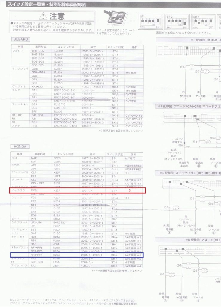
I found there is Honda car model called RF3 and RF4 which share K20A engine.
When I compare the ECU wiring and the connectors layout to the RF3/RF4 HKS SLD installation diagram, I found they are very similar to DC5, then I drilled down to check the wiring color on SLD manual and DC5 ECU wiring, the color does match (written in Japanese but basically Chinese can read and understand easily).
Here is my summary, but I am not 100% confident, so need someone who is good at ECU or who got experienced to advice here.
Connector A (31P)
Terminal 3
YEL/BLK
ECM Power
-> SLD Type 1 - Red Wire
-> Tap on
Connector A (31P)
Terminal 24
BRN/YEL
ECM Ground
-> SLD Type 1 - Black Wire
-> Tap on
Connector C (22P)
Terminal 15
BLU
NC (Countershaft Speed Sensor)
-> Cut the wire
-> ECU Side -> SLD Type 1 - Yellow (VSS Output)
-> Harness Side -> SLD Type 1 - White (VSS Input)
Connector E (31P)
Terminal 25
BLU/WHT
VSSOUT (To Speedometer, I guesS)
-> Unchange
-> SLD Type 1 - Blue (Not used/connected)

Recently, I have bought a DC5 and found this is more useful and practical for it. Not sure whether I would hit the speed cut or not in track in future, but it is good to prepare if I need to.
Found another thread about that but not much technical detail in it. Other brand/model of sport cars have lot of info on how to install HKS SLD Type 1 but not on DC5.
http://www.itr-dc5.club/forum/index.php?/topic/42216-remove-the-flange-of-180-km-h/
I have research mainly on below two links, one is K20A ECU wiring, another one is DC5 HKS SLD written in German (but can translate it).
http://www.k20a.org/forum/showthread.php?t=230
http://www.maxrev.de/integra-dc5-hks-sld-delimiter-t226026.htm
After I read the SLD Type 1 manual, it showed some car installation guide but just don't have one for DC5 (FD2 they have it, but FD2 ECU connectors are quite different).
I found there is Honda car model called RF3 and RF4 which share K20A engine.
When I compare the ECU wiring and the connectors layout to the RF3/RF4 HKS SLD installation diagram, I found they are very similar to DC5, then I drilled down to check the wiring color on SLD manual and DC5 ECU wiring, the color does match (written in Japanese but basically Chinese can read and understand easily).
Here is my summary, but I am not 100% confident, so need someone who is good at ECU or who got experienced to advice here.
Connector A (31P)
Terminal 3
YEL/BLK
ECM Power
-> SLD Type 1 - Red Wire
-> Tap on
Connector A (31P)
Terminal 24
BRN/YEL
ECM Ground
-> SLD Type 1 - Black Wire
-> Tap on
Connector C (22P)
Terminal 15
BLU
NC (Countershaft Speed Sensor)
-> Cut the wire
-> ECU Side -> SLD Type 1 - Yellow (VSS Output)
-> Harness Side -> SLD Type 1 - White (VSS Input)
Connector E (31P)
Terminal 25
BLU/WHT
VSSOUT (To Speedometer, I guesS)
-> Unchange
-> SLD Type 1 - Blue (Not used/connected)